 International
 Singapore
 Malaysia
 Thailand
 Vietnam
Không có sản phẩm trong giỏ hàng!

Real-Time IoT Room Monitoring on Maker Pi Pico Using pyRTOS
Overview
In this project, we're going to build a device that can monitor a room's temperature, humidity, and air quality using Grove sensors on Maker Pi Pico. Since pyRTOS makes adding new features easier for us, we will be adding more and more tasks to the system. For example, detecting motion, sound, displaying data on OLED display, and even IoT tasks which will send data to Blynk. The program flowchart will be as below.

Before we begin...
If you haven't read the tutorial on how to install pyRTOS on your Maker Pi Pico, you can check it out here. In this project, we will be using CircuitPython. You can download the .uf2 file to install CircuitPython on your Maker Pi Pico here.
Components Used
Part 1: Adding Tasks for Sensors & Display
In this part, we're going to add sensors to the system. We'll start with the easier ones and then add the more complex ones. With pyRTOS, you can manage your added functionalities easier since they are divided by tasks. Remember to import necessary libraries and declare global variables at the top of your code. Usually, the list will grow as you add more tasks to the system.
import pyRTOS
import board
import digitalio
import adafruit_dht
import analogio
import busio
import adafruit_ssd1306
import adafruit_requests as requests
import adafruit_espatcontrol.adafruit_espatcontrol_socket as socket
from adafruit_espatcontrol import adafruit_espatcontrol

temp = 0.0                                      # Initialize global variables
humidity = 0.0                                  # Initialize global variables
air = 0.0                                       # Initialize global variables
motion = 0                                      # Initialize global variables
sound = 0                                       # Initialize global variables
First, we'll add the (Passive Infrared) PIR motion sensor to the program. Connect the Grove PIR Motion Sensor to the GROVE 1 port of the Maker Pi Pico. This port uses the GP1 for the digital input.
def DetectMotion(self):
    PIR = digitalio.DigitalInOut(board.GP1)     # Setup PIR sensor pin
    PIR.direction = digitalio.Direction.INPUT   # Setup pin as digital input
    global motion                               # Use the global variable
    yield

    while True:
        if PIR.value:                           # If the PIR sensor detects motion
            motion = 1                          # Update the global variable
        yield [pyRTOS.timeout(0.1)]             # Delay in seconds (Other task can run)
Next, we'll add the Sound Sensor to the system. Connect the Grove Sound Sensor to the GROVE 2 port of the Maker Pi Pico. This port uses the GP3 for the digital input.
def DetectSound(self):
    mic = digitalio.DigitalInOut(board.GP3)     # Setup sound sensor pin
    mic.direction = digitalio.Direction.INPUT   # Setup pin as digital input
    global sound                                # Use the global variable
    yield

    while True:
        if mic.value:                           # If the sound sensor detects loud sound
            sound = 1                           # Update the global variable
        yield [pyRTOS.timeout(0.1)]             # Delay in seconds (Other task can run)
We'll also add the Grove Air Quality Sensor. Connect the sensor to the GROVE 6 port of the Maker Pi Pico. This port uses the ADC1 on pin GP27 for analog input. We need to convert the received analog value into percentage as shown in the code below. Higher percentage means higher pollution.
def AirQuality(self):
    airq = analogio.AnalogIn(board.A1)          # Setup air quality sensor on pin A1
    conv = 330 / (65535)                        # Formula to convert analog value to percentage
    global air                                  # Use the global variable
    yield

    while True:
        air = round((airq.value * conv), 2)     # Round off the value to 2 decimal places and update
        yield [pyRTOS.timeout(0.2)]             # Delay in seconds (Other task can run)
We'll add the DHT11 Temperature and Humidity Sensor. Connect the sensor to the GROVE 3 port of the Maker Pi Pico. This port uses GP5 as the digital input. However, reading the DHT11 is not as straightforward as the previous sensors. It has its own protocol to send data to the microcontroller. So, we'll use the library provided in the Cytron's Github for the DHT11 for CircuitPython.
def ReadDHT11(self):
    dhtDevice = adafruit_dht.DHT11(board.GP5)
    global temp
def ReadDHT11(self):
    dhtDevice = adafruit_dht.DHT11(board.GP5)   # Setup DHTT11 on pin GP5
    global temp                                 # Use the global variables
    global humidity
    yield

    while True:
        try:
            temp = dhtDevice.temperature        # Update the global variables
            humidity = dhtDevice.humidity
        except RuntimeError as error:           # Errors happen fairly often,
            print(error.args[0])                # DHT's are hard to read,
            continue                            # just keep going
        except Exception as error:
            dhtDevice.exit()
            raise error
        yield [pyRTOS.timeout(1)]               # Delay in seconds (Other task can run)
Lastly, we'll add the OLED Display to show the information in real time. Connect the OLED Display to GROVE 5 port of the Maker Pi Pico. This port uses the I2C 0, which is the GP9 (SCL) and GP8 (SDA). we'll use the library provided in the Cytron's Github for the OLED for CircuitPython.
def DisplayOLED(self):
    i2c = busio.I2C(board.GP9, board.GP8)               # Setup I2C pins with GP9 and GP8
    oled = adafruit_ssd1306.SSD1306_I2C(128, 64, i2c)   # Setup OLED display using the above pins
    global temp                                         # Use global variables
    global humidity
    global air
    yield

    while True:
        oled.fill(0)                             # Erase the OLED display

        oled.text('Temperature = ', 0, 0, 1)     # Write the data
        oled.text(str(temp), 90, 0, 1)
        oled.text('Humidity = ', 0, 25, 1)
        oled.text(str(humidity), 90, 25, 1)
        oled.text('Air Pollution = ', 0, 50, 1)
        oled.text(str(air), 90, 50, 1)

        oled.show()                              # Show the written data
        yield [pyRTOS.timeout(0.5)]              # Delay in seconds (Other task can run)
You can try one task at a time, use the print command to show the data and check whether it is working. Don't forget to add the tasks and run pyRTOS at the end of your code.
pyRTOS.add_task(pyRTOS.Task(DetectMotion))  # Add Tasks
pyRTOS.add_task(pyRTOS.Task(DetectSound))
pyRTOS.add_task(pyRTOS.Task(ReadDHT11))
pyRTOS.add_task(pyRTOS.Task(AirQuality))
pyRTOS.add_task(pyRTOS.Task(DisplayOLED))
# pyRTOS.add_task(pyRTOS.Task(SendData))

pyRTOS.start()                              # Start pyRTOS
Part 2: Adding IoT Task (Blynk 2.0)
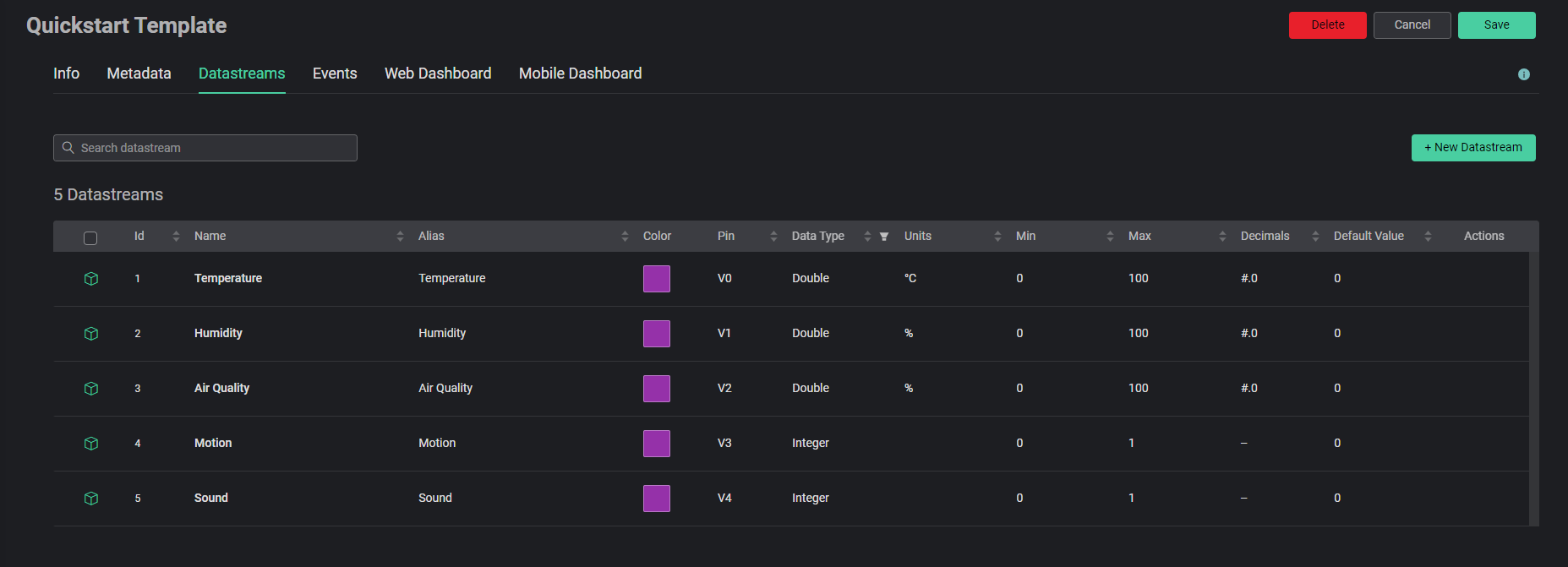
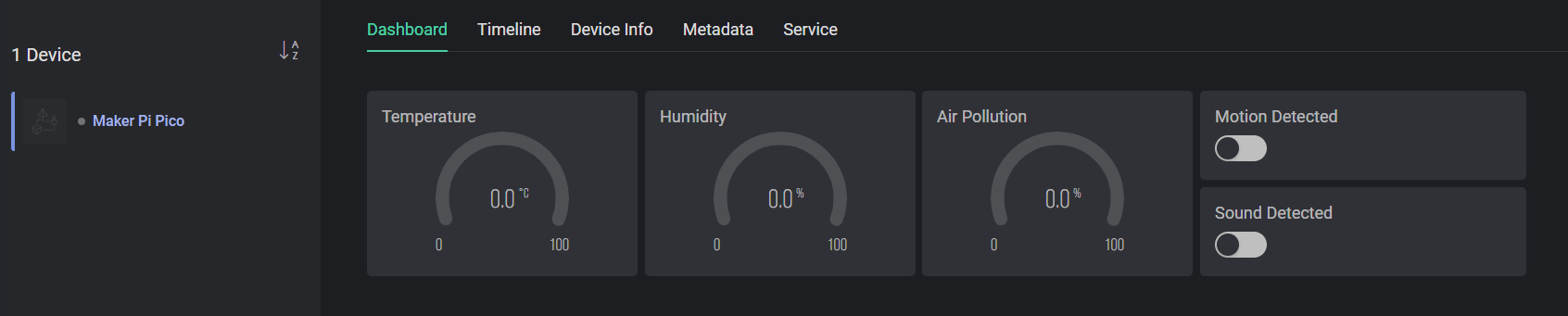
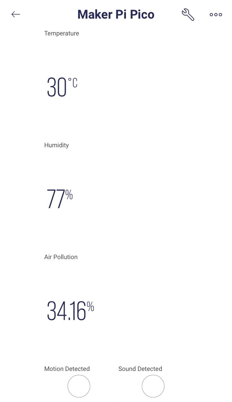
For starters, we need to copy the IoT library to the Maker Pi Pico lib folder. We'll also need the secrets.py file in order to connect to the Blynk cloud. To begin, sign up and login to Blynk. After logging in, add a new template. After adding a template, you can add a new device. Next, edit the dashboard to start adding virtual pins in the datastream. Finally, modify the dashboard to display the values of the virtual pins. Your Blynk is all setup! Your datastream list, web dashboard, and mobile dashboard should look something like this after setup.
You will need to modify the secrets.py file to set your SSID, password, and Blynk auth token. You can find the auth token in the "device info" tab in the figure above. Connect the ESP01 to its port on Maker Pi Pico. The port uses GP16 as TX and GP17 as RX.
def SendData(self):
    global temp
    global humidity
    global air
    global motion
    global sound
    try:
        from secrets import secrets
    except ImportError:
        print("All secret keys are kept in secrets.py, please add them there!")
        raise
    # Initialize UART connection to the ESP8266 WiFi Module.
    RX = board.GP17
    TX = board.GP16
    uart = busio.UART(TX, RX, receiver_buffer_size=2048)  # Use large buffer as we're not using hardware flow control.
    esp = adafruit_espatcontrol.ESP_ATcontrol(uart, 115200, debug=False)
    requests.set_socket(socket, esp)
    print("Resetting ESP module")
    esp.soft_reset()
    # Connect to WiFi
    print("Connecting to WiFi...")
    esp.connect(secrets)
    print("Connected!")
    yield

    while True:
        # Update the blynk datastream using HTTP GET requests
        requests.get("https://blynk.cloud/external/api/update?token=" + secrets["blynk_auth_token"] + "&v0=" + str(temp))
        yield [pyRTOS.timeout(0.5)]           # Let other tasks run
        requests.get("https://blynk.cloud/external/api/update?token=" + secrets["blynk_auth_token"] + "&v1=" + str(humidity))
        yield [pyRTOS.timeout(0.5)]           # Let other tasks run
        requests.get("https://blynk.cloud/external/api/update?token=" + secrets["blynk_auth_token"] + "&v2=" + str(air))
        yield [pyRTOS.timeout(0.5)]           # Let other tasks run
        requests.get("https://blynk.cloud/external/api/update?token=" + secrets["blynk_auth_token"] + "&v3=" + str(motion))
        yield [pyRTOS.timeout(0.5)]           # Let other tasks run
        requests.get("https://blynk.cloud/external/api/update?token=" + secrets["blynk_auth_token"] + "&v4=" + str(sound))
        yield [pyRTOS.timeout(0.5)]           # Let other tasks run
        # Reset the global variables
        if motion:
            motion = 0
        if sound:
            sound = 0
        yield [pyRTOS.timeout(0.5)]           # Delay in seconds (Other task can run)
Don't forget to import the necessary libraries. If you still encounter errors like "name 'something' is not defined" or module not defined even if you have already copied the file to your Maker Pi Pico, try to move the file in or out of the lib file of the Maker Pi Pico. Finalized code used in this tutorial can be found here.
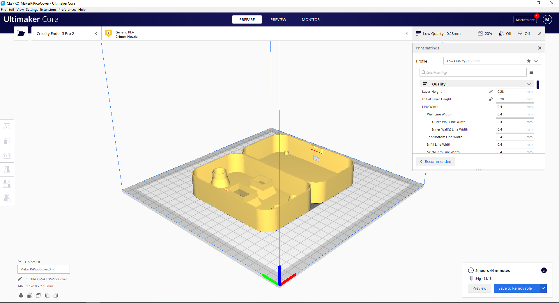
Part 3: 3D Printing The Cover (Optional)
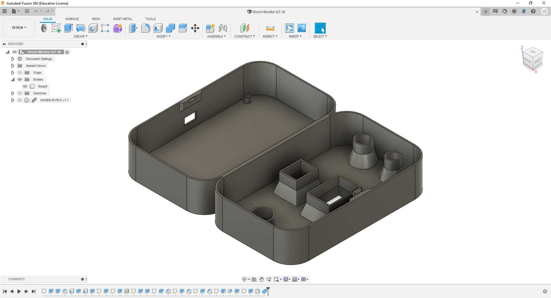
Now that the system works on the software level, the hardware needs to be tidied up so that it looks like a proper device. The cover is designed in Fusion 360 as a single part with a flat hinge and snap-close features. The model is sliced in Cura with default settings for Ender 3 at 0.28mm layer height. You can download the CAD files of the part here. The part is designed to fit with the sensors without any screws or glue. You will only need screws to mount the Maker Pi Pico to the cover. If the holes or the snap close feature are too tight/loose when you 3D print it, you might need to modify the dimensions of the holes. Tune your initial horizontal expansion setting before printing this. Mine was -0.15mm.
Related Products
 Bán chạy
Maker Pi Pico: Phiên bản đơn giản của Raspberry...
316,800₫ 288,000₫
x 1 đơn vị