 International
 Singapore
 Malaysia
 Thailand
 Vietnam
Không có sản phẩm trong giỏ hàng!
It has been an exciting year back in 2013. Besides launching rero in indiegogo.com, we have been busy with the development for Robot Head To Toe, not to forget the improvement and on-going development needed for rero. One of our new products is smart LED. Have you ever wanted to add LED to your project but think twice when you see all the wires needed? Well, now you should think again.
[youtube]http://www.youtube.com/watch?v=FFCphBvp5RM[/youtube]
With WS2812B LED, only 1 pin is needed to control as many RGB LED as you want. This is SMD (Surface Mount Device) LED that integrates a driver controller alongside with RGB (Red Green Blue) into a tiny 5050 package controlled through a single wire; even better, it can be daisy chained and individual controllable. In simple words, you can control this RGB LED, single unit, or chained it up to as many you want, and you still able to control each and every LED individually. All this can be done with 1 digital output pin from your microcontroller. Isn’t that amazing!!
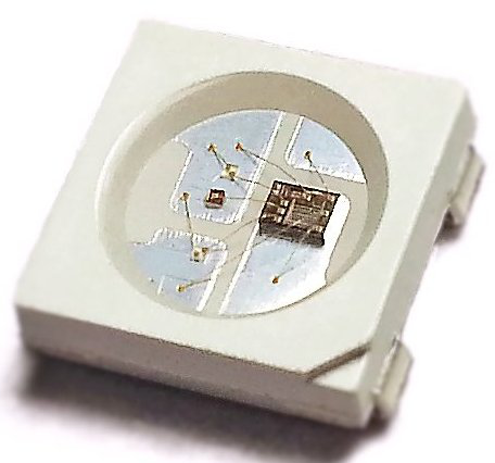
If you look closely to the picture above, you can actually see the bonding of wires to different segments (Red, Green, Blue) from the driver chip. All this is on a single 5050 SMD package LED. For the time being, we only offer the breakout board that mounted with single WS2812B LED :). We are developing more ofRainbowBit product, keep a close look at our front page. The flexible LED strip (RainbowStrip) is here, we are excited too.
Nature of RainbowBit (WS2812B) LED:
- Not all RGB LEDs are RainbowBit (WS2812B). We named this RGB LED because it is like rainbow Anyway the library and interface can be applied to WS2811 and WS2812 LED.
- Beware! RainbowBit will require some sort of controller (such as Arduino) to operate/light up. It will not light up by itself even the power is connected, not like a normal LED. However, fear not! We do provide guidance and example code to use it, and you should create your own lighting magic! You will love it.
- Do understand this, controller push bit by bit to 1st RainbowBit and further to 2nd and so on and so forth. This requires time, therefore, you are not able to get a fast refreshing rate if there are too many RainbowBit. But do not get me wrong, there are still plenty of projects that you can do with RainbowBit.
- Not every controller can handle the timing requirement of the serial protocol needed for RainbowBit (WS2812B). Some controller such as Netduino and Raspberry Pi might have hard time to reliably achieve this requirement. Even Arduino or PIC running RainbowBit function cannot be distracted with interrupt which might affect the timing.
Features and Specifications of RainbowBit:
- Ready with WS2812B LED and decoupling cap
- Every RainbowBit is tested before being shipped
- Operating voltage, VDD or VCC: +3.5V to +5.5V
- Built-in signal reshaping circuit
- 256 level of brightness (PWM) for each color (RGB), offering 16777216 color display
- RainbowBit is designed to be cascaded side by side
- Input signal voltage: -0.5V to VDD+0.5V
- Each RainbowBit can draws up to 60mA at maximum brightness white(RGB all at full brightness)
- Each color segment at full brightness will draws around 20mA
1st thing 1st, the Hardware (RainbowBit)
Yes, is time to hook this colourful LED and get some rainbow out of it! All you need is +5VDC supply and a digital output pin which you could program to output the timing required. As the example sketch provided is using BBFuino, we will follow it. The library for RainbowBit developed by Adafruit (credit goes to them). We modified the example and created another example, RainbowBit_Example. The sketch is compatible with Arduino UNO, Arduino PRO Mini, Arduino Mega, Arduino Nano, and more Arduino main board series. RainbowBit_Example uses four RainbowBit modules, but you can always use one to start if you wanted to try it. Let’s hookup!
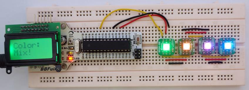
RainbowBit connected to BBFuino
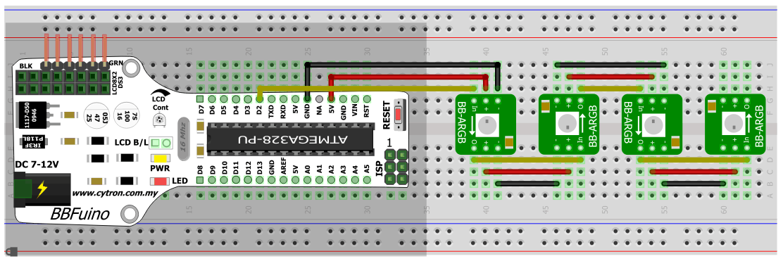
If you refer to the diagram carefully, the RainbowBit is being connected in daisy chain format. Only the 1st Rainbowbit is connected to BBFuino. While the outputs (- , + and O) of 1st RainbowBit is connected to inputs of 2nd RainbowBit. Please do check the arrow direction on RainbowBit, it indicates the direction of control flow from BBFuino or your controller.
The “In” of 1st RainbowBit should be connected to pin D2 of BBFuino. If you are using other type of Arduino board, simply make the same connection as shown:
- GND from Arduino to “-” of 1st RainbowBit
- 5V from Arduino to “+” of 1st RainbowBit
- D2 from Arduino to “In” of 1st RainbowBit
Note: Is a good practice to connect the GND (-) pin before anything else.
Not to forget, you will need to solder header pin of your choice to RainbowBit. Try to get 1×40 straight header pin, or 1×40 right angle header pin, or any connector that you like.
With the assumption you have been using Arduino IDE, I will proceed with library installation. If you are new, please do visit the getting started guide with BBFuino here. Download the library and example sketch here. Unzip it and move the folder to Documents\Arduino\libraries. Open Arduino IDE, and goto File -> Examples -> Adafruit_NeoPixel -> RainbowBit_Example. Compile and load it into BBFuino.
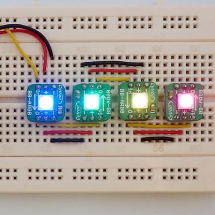
This is what the example code does:
- RainbowBit will illuminate in Red light from 1st to 4th module
- Change the 4th to 1st RainbowBit module into Green
- Change 1st to 4th RainbowBit into Blue
- Change 4th to 1st RainbowBit into White
- Blank all from 1st to 4th RainbowBit and
- Lastly, a rainbow sequence through all 4 RainbowBit
Hope you have fun with the result, if you cannot get the expected result, please check:
- Polarity, center pin of RainbowBit is +5V, not 3.3V or Vin of Arduino.
- D2 of Arduino should be connected to “In” of RainbowBit, not “O”.
- Make sure the 5V is stable. Try putting a 100uF E cap between 5V and GND.
- Connections on the breadboard, is it loose?
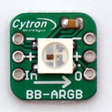
RainbowBit Layout
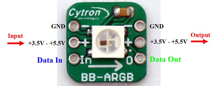
The centre white color chip is the WS2812B RGB LED chip and the brown color chip on top is decoupling cap (0.1uF).
RainbowBit is designed to be cascaded side by side. If you wanted to build your own LED strip, you will only need 3 wires from the controller board to 1stRainbowBit, and another 3 wires from output of 1st RainbowBit to input of 2nd RainbowBit, so on and so forth until you are out of wires or RainbowBit. You can even solder it directly as shown.
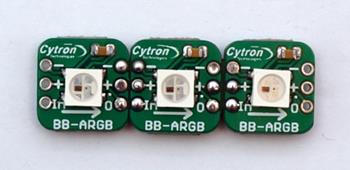
Top View: RainbowBit
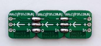
Bottom View: RainbowBit
Make sure the data direction arrow is pointing at the same direction.
Power requirement
RainbowBit should be powered with +5VDC. Lower voltages are always safe, but not necessary acceptable. Even though it might function, the light from LED will be slightly dimmer. The minimum voltage is +3.5V, we have yet tested it with 3.3V system, but if the voltage drops below a certain level, RainbowBit will start to display wrong color. Besides, power voltage will drops across wire due to resistance. Although the resistance is small in wires, it make different if it is long. This means, power voltage near the end of wire will be lower than the beginning of wire. To overcome the power voltage drop at the end of the RainbowBit string (if it is very long), you can actually connect another power source at the end or middle of wire, make sure the voltage level is same. RainbowBit does not care which direction they receive power from, though the data only flow in one direction (follow the arrow). You can simply measure the voltage at beginning of string and at end of string by using multimeter. Just compare the result. We did a RainbowBit string in our office with the length of 5.5 meters. The voltage drops around 0.4V at the end of string.
How about current draw? What is the current spec of power supply you should use? This is easier to calculate Assuming a RainbowBit requires 60mA in full brightness of white color (All RGB at full brightness), just multiple it with number of RainbowBit in the system. As an example, 30 RainbowBit in a chain, maximum current draw will be:
30 x 60mA = 1.8A.
You should get power supply of at least 2A considering current draw by microcontroller and other components. Nonetheless, you can always power the RainbowBit chain with lower current power source if you manage to control the brightness (PWM) of LED. Not all RainbowBit emits white color all the time
Which power supply/source should I use?
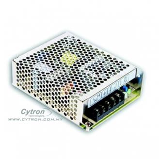
- Switching Power supply, with output of 5V, example this power supply. It provides high current and stable voltage output. But always connect a 470uF >10V Electrolytic Cap parallel with the output. This prevents potential inrush current which might damage the 1st RainbowBit.
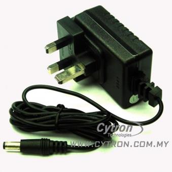
- AC to DC adapter, 5V 1A:
- Use the power from microcontroller 5V regulator. Most of microcontroller board including BBFuino, Arduino UNO, SK40C comes with 5V voltage regulator. It can always be used for RainbowBit. Do bear in mind; generally, this type of voltage regulator (linear regulator) is rated under 1A or even under 500mA. So if the brightness of RainbowBit is being controlled, you can still power up to 20 of it in chain.
- Use single cell 18650 Li-ion or Li-po rechargeable battery. A single cell Li-ion or Li-po battery is rated at 3.7V (full charged at 4.2V), this is just nice to power up most of low power microcontroller and RainbowBit. 5 to 8 RainbowBit will work fine.

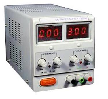
- Bench top adjustable power supply. CAUTION!! Most of bench top power supply will produce high voltage spike when initially switch ON, so if you plan to use this, do not connect the RainbowBit directly. Please switch the power supply ON and let the voltage to stabilize, only connect the RainbotBit, always the GND first.
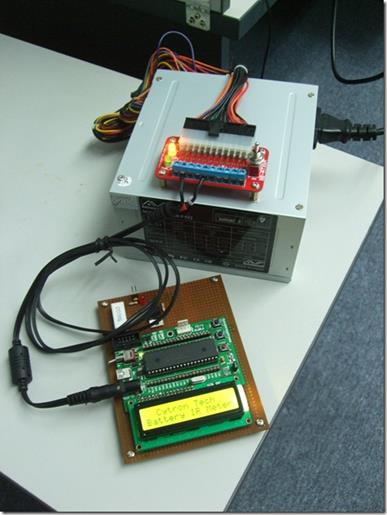
- Desktop ATX Power supply with proper hacking. ATX power supply is being used in desktop computer and offers +3.3V, +5V and +12V with very stable voltage output and high current. With proper hacking, this is very low cost yet stable option to power up long string of RainbowBit. We have been using this power supply with BB-ATXRA in our laboratory for several projects. Check out our tutorial on how to use it.
How does it work? The Protocol!
We reach the magic area of RainbowBit. You can ignore this section if you are beginner and using library. We will be talking about the protocol of RainbowBit, what make it to be addressable individually and able to be chained up. If you wanted to write your own code, come in!
I extract the data from the WS2812B datasheet, in case I made mistake, please do go back to the datasheet.
RainbowBit/s is/are controlled by a simple, yet timing critical one wire protocol on the input signal line. Each RainbowBit have 3 bytes (24-bit) of data to control the PWM/brightness of Red, Green and Blue LED (8-bit each). As you might have know, color LED is combination of Red, Green, Blue LED integrate together closely. The color of LED is determined by the brightness of these 3 LEDs. These values (brightness of three LED) should be sent into RainbowBit in GRB (Green, Red, Blue) sequence, NOT RED, GREEN, BLUE!!
The first 24-bit color brightness transmitted out applies to first RainbowBit LED which is the closet to the microcontroller, with the MSB (Most Significant Bit) goes first. While the second 24-bit color brightness transmitted applies to the next LED or 2nd LED in the string, and so on.
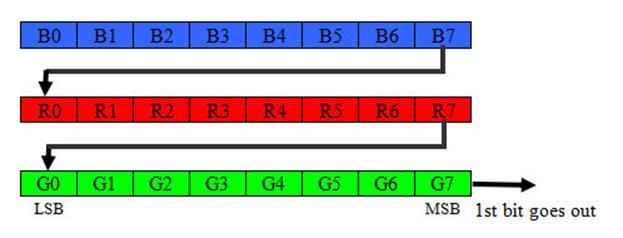
Sequence of 24-bit for RainbowBit.
As the diagram illustrates, 1st byte sent out from microcontroller should be brightness for Green LED, and MSB (bit-7) goes first, followed by 8-bit of brightness for Red LED and further Blue LED. Not to forget, this 24-bit data is for one RainbowBit, if you have more RainbowBit in chained, you need to continue sending data. To update all the RainbowBits in the string, all the colors data should be sent out at once (24-bit + 24-bit + 24-bit……) with no pauses. If less data is being sent out than the number of RainbowBit in the string, some RainbowBit near the end of string will not be updated. As example, if you have 20 RainbowBit in your string and you want to update all of the RainbowBit (most of the time you want to do that), you should send 480 bits (24-bit x 20 RainbowBit) of data out as pulses and then hold the line low for at least 50us (micro seconds) or more.
Now let’s look at lower layer of the communication. Since there is only 1 wire, there must be a special way to transmit logic 1 and 0. During idle state (no data), the signal line should be low. To transmit color brightness, a series of high pulses are needed to be sent out. Each high pulse encodes a bit: A short pulse (0.35µs) represents a zero (logic 0), while a long pulse (0.9µs) represents a one (logic 1). The time between adjacent rising edges should be 1.25µs. After bits for all RainbowBit are sent, the signal line should be held low for at least 50µs to send a reset command, which makes the new color data to take effect. From experiments, the pulse widths do not have to be precise, however, the high pulse period plays an important factor to determine the logic.
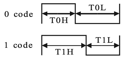
Logic pulses
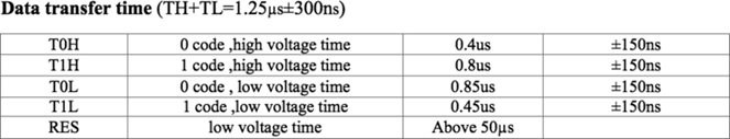
Logic timing requirement
Note that there’s around 20% to 25% of “grey area” to play around from timing table. ±150ns for high and low stage, giving us total of ±300ns for tolerance. So if your code cannot output bit at the recommended timing, it might be still working :). Although there is tolerance, most of the library is written using Assembly language to ensure the correct timing. Besides, to ensure the timing is met, interrupt is disabled during the data is being sent out. Therefore, Servo library in Arduino does not work well with RainbowBit functions. If you have to use interrupt, you may modify the code to enable interrupt during low state of signal which might works, but we do not sure on that.
Alternative libraries
Yes, we like to use RainbowBit with other type of microcontroller too. For the time being, we have tested the NeoPixels library from Adafruit Industries, working fine! Kudos to them. However, since the library is written with mix of Assembly language due to the requirement of timing, it might not works on Netduino, ChipKit or other “Arduino-like” development boards. Yet, it does work with common Arduino boards such as UNO, Leonardo, Mega, DUE, Micro, Pro-Mini, Nano, and BBFuino.
How about other type of microcontroller or boards? We have yet to explore other libraries, but here are some links that might worth a look:
- WS2811 RGB LEDs from insomnialighting – Uses SPI to transmit data, PIC MCU based with CCS C compiler.
- Controlling RGB LED WS2811 with PIC16F877A – Sanjeev’s Blog, written in Assembly Language, compiler with MPLAB X IDE v1.85, PIC16F877A at 20MHz.
- Discussion of WS2811 with PIC MCU – Forum.
WS2811 vs WS2812 vs WS2812B
You might have seen WS2811, WS2812/S and WS2812B in the market and not sure can the library works with this chip? WS2812B is the latest RGB LED with integrated chip which is revised from WS2812. WS2812 is 6 pins while WS2812B is 4 pins. Both WS2812 and WS2812B is build base on WS2811. WS2811 is an external LED driver chip.
Why we choose WS2812B? According to the manufacturer, WS2812B is better in term of:
- Better mechanical package design – WS2812B only has 4 pins vs 6 pins in WS2812/S. This simpler design prevent shorts and offers improved voltage drop and thermal dissipation by allowing for larger power and ground planes on the PCB.
- Higher Brightness – The WS2812B is able to produce a much higher brightness than the WS2812/S.
- Safety performance comparison – WS2812B comes with reverse polarity protection at the power line. It will survive reverse connection of power.
- Internal structure improved – WS2812B has a better structure than WS2812. The control circuit and the RGB LED have been separated, it has a better heat dissipation performace. The control and LEDs work independently, one does not relate to the other, line distance is shorter and makes the work more stable .
Well, that is from us. We will try to update more library and RainbowBit product line.
BUY